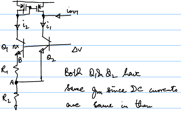
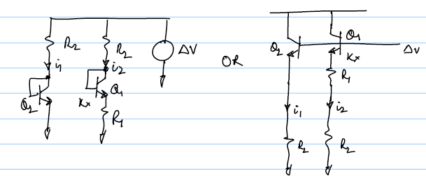
Cell 1
The basic cell has a structure as shown below:
Analysis
We have:Putting these in the 1st equation we have:
Also
$[g_m(Δv-v_B)+g_m(Δv-v_A)]R_2=v_A$. From this we can solve for $v_A$ and we have:Also
$v_B-v_A=g_m(Δv-v_B)R_1$. From this and using the $v_A$ value from (2) we have:Substituting
$v_B$ from (3) and $v_A$ from (2) into (1) we have:Dividing by
$Δv$ and simplifying we have:By substituting
$g_m={\ln n}/R_1$ and taking approximations we have:Useful numbers
Normally the n factor is set to 8 since that allows good layout. With n = 8 we haveEven if n=4 we have
$G_M=0.4/R_2$ which is still close with about 25% error. So the number $1/{2R_2}$ is good to keep handyCell 2
This alternate topology has a structure as shown below:
Analysis
Both topologies follow the same analysis:Therefore we have:
If
$g_mR_2≫1$ then we can approximate $G_M$ as:Useful Numbers
Remember that the bandgap voltage is about 1.2V and Vbe is about 0.6V so in this case we have:So for n=8 we have
$R_2=11.1R_1$, putting this in the $G_M$ equation we haveComparing the Transconductances
$$({g_m^2R_1}/{1+g_mR_1+2g_mR_2+g_m^2R_1R_2})_I◌({g_m^2R_1}/{1+g_mR_1+2g_mR_2+g_m^2R_1R_2+g_m^2R_2^2})_{II}$$It is clearly seen than the
$G_{M-I}>G_{M-II}$ because of the extra term $g_m^2R_2^2$ in the denominator. Hence the topology 1 always provides better accuracy by making the effects of mismatch and offset for the same bias currents lower.From the numbers we also see that for n=8 the 1st topology provides 6 times more
$G_M$.