DNL
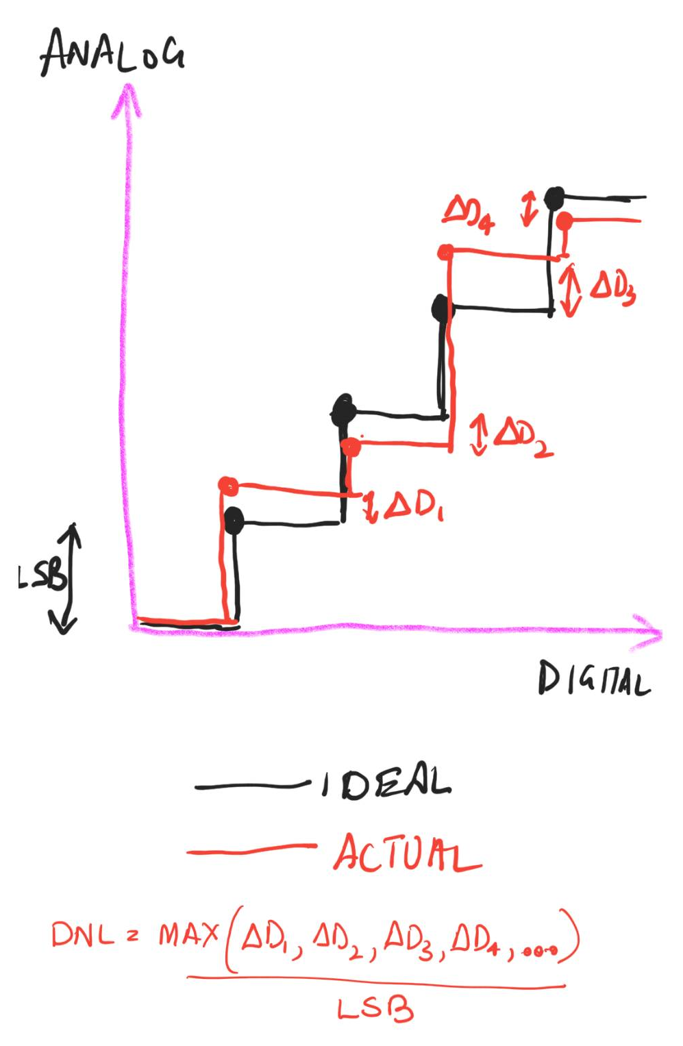
DNL is an abbreviation for Differential Non Linearity. It is a measure of the maximum deviation over the whole range of the step in the Analog input/output from an ideal 1 LSB step. This report shows some good graphs to understand DNL.As an example if supplose a DAC has a LSB step of 1mV so that means that every next input code the output voltage should increase by exactly 1mV. But depending on the circuit non linearities/mismatches and operating point the steps may be like 0.991mV, 1.001mV, 0.99mV.... So DNL is given by:
This is shown int he diagram below:

Cadence
The DNL for a DAC which can be simulated through its range using a DC sweep simulation and using a simple formula in Cadence Calculator. Here is the procedure to do that:- Create a test bench with the DAC with all sources with DC values so that the DC simulation can power up.
- The input to the DAC can be given by a ADC created using verilog AMS. The following code can be used to create a ADC that can simulate in a DC simulation:
-
- Now connect the output digital bus of this ADC symbol to the DAC input.
- The input of the ADC is connected to a voltage source whose DC voltage is set to a variable like "vin"
- The parameters of the ADC should be set as follows:
- vlogic_high - Set to the logic high level of the bus
- vlogic_low - Set to the logic low level of the bus
- vref - This is the most important parameter for correct simulation. Calculate it as follows. If the LSB for this ADC you want to set as L then the vref = L*2^(NUM_ADC_BITS). So for example for an LSB of 5mV for an 8 bit ADC the vref should be set to 1.28V
- Now run a DC sweep simulation where you sweep the "vin" variable from a value less than L with a step of L all the way to vref
- Since we step with L every DC sweep evaluation point will generate a new code and hence a new output from the DAC. So the DAC output will look like a perfectly straight line with a a constant slope.
- Now use this formula to calculate the +ve and -ve DNL and the absolute
-
$DNL_+$=ymax(deriv(VS("/OUT"))*VAR("vinstep")/VAR("LSB")-1)$$}}} -
$DNL_-$=ymin(deriv(VS("/OUT"))*VAR("vinstep")/VAR("LSB")-1) - DNL=ymax(abs(deriv(VS("/OUT"))*VAR("vinstep")/VAR("LSB")-1))
- Here LSB is the output voltage LSB value.
- vinstep is L described above
- You may have to clip VS("/OUT") if the sweep in vin exceeds the DAC input range and you may have to clip deriv(VS("/OUT")) to remove the 1st point. It can be clipped from offset+vinstep to (2^bits-1)*vinstep+offset. Where offset it the sweep starting value (less than L)
-
For a DAC if the output at 0 code (all 0) is 0 then LSB = Vo/(2^bits-1) where Vo is the full scale output (at all 1s)
For a DAC if the output at 0 code (all 0) is 1 Vi then LSB = (Vo-Vi)/(2^bits-1). If Vi = 1 LSB then this is equivalent to LSB = Vo/(2^bits)