The network
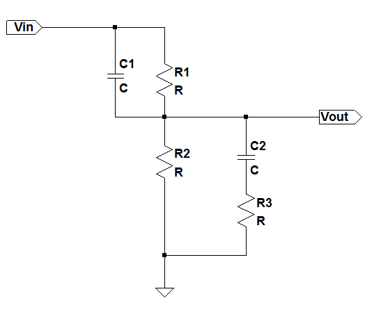
The following circuit shows the lead-lag network which creates 2 poles and 2 zeroes:
Solution
The$V_{in}$ to $V_{out}$ transfer function can be written as:This can be simplified to:
Zeroes and Poles
So we see the 2 zeros created are:The 2 poles can be calculated if we solve the denominator which can we written as:
or
If we substitute the following:
we can write (3) as:
We can solve for s as:
Now to simplify further we need to see the relative magnitudes to decide what terms can be neglected. Comparing A and B we can clearly see that if the circuit time constants are lower than even a milli second A ≪ B. That is because A is a product of 2 time constants while B is a time constant. Usually the network is designed to have 1 time constant much smaller than the other. So consider the case when one time constant is 100 times larger than the other. For example
$R_3C_2 ≫ R_1||R_2C_1$. This means that the magnitude of $A/B^2$ = 100/10000 or $4A/B^2=4/100$. So $B^2$ is still 25 times larger than 4A. So from this point on the assumption and approximation that we take is:
One time constant in the circuit is more dominant than the other one.
So now we can approximate the poles now as:
So substituting the values of A and B in we get the final poles of the circuit as:
If
$C_1≪C_2$ and $R_3≪R_1||R_2$ then we can approximate the poles as:See Also
- Compensation Techniques
- The book Frequency Compensation Techniques for Low-Power Operational Amplifiers (The Springer International Series in Engineering and Computer Science)
has good chapter on compensation analysis of multi stage opamps.
- The book Op Amps for Everyone, Fourth Edition
has a good chapter on different networks for compensating opamps