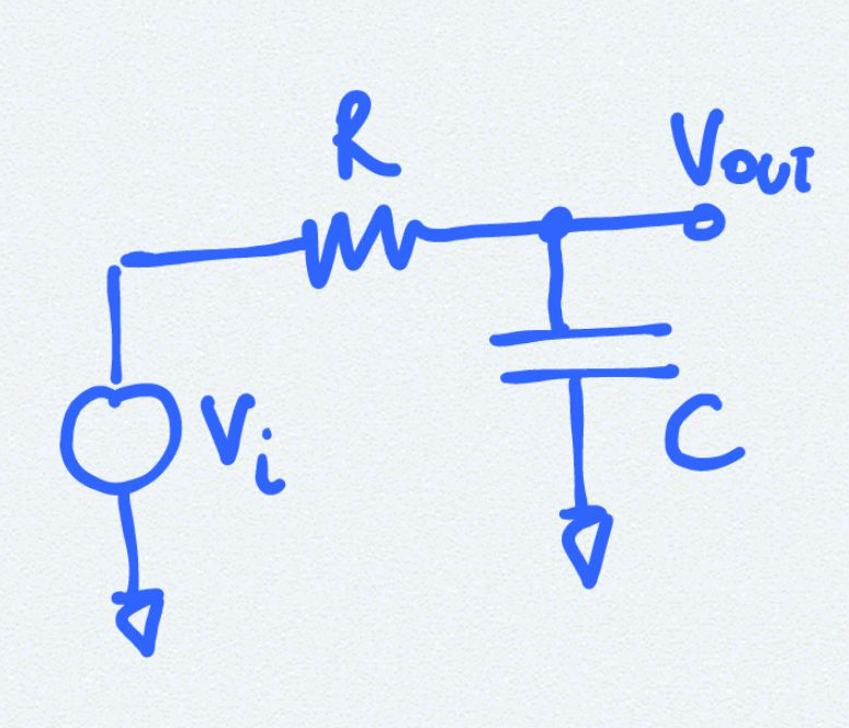
Circuit Diagram

Analysis
Although this is a very simple and well known circuit some interesting questions here and results here that we derive here is- What happens when
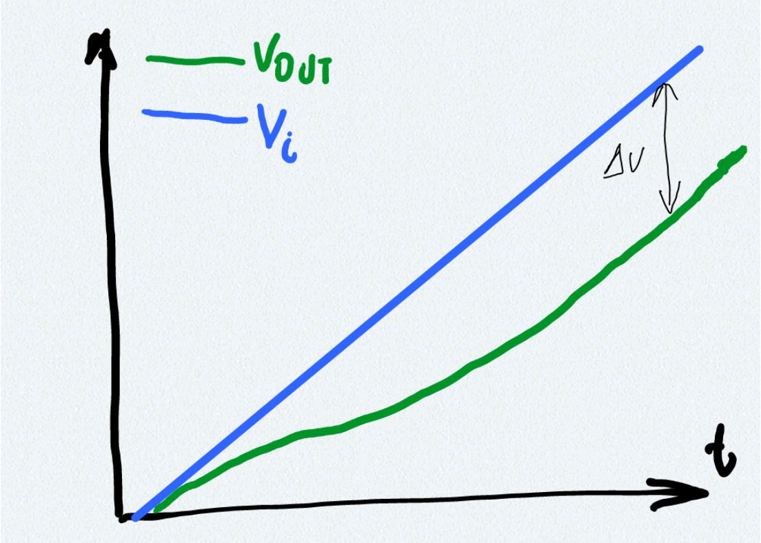
$V_i$is a ramp rather than a step. - How does the output voltage behave different ramp slopes

Why are those important? If we know how soon the output catches up to a ramp and what is the voltage lag we can determine the RC values that give the desired response to a ramp input encountered so often in circuits.
Let
$V_i=Mt$ where M is the ramp slope and t is time so we have:Solving this differential equation for
$V_{out}$ by multiplying with $e^{t/{RC}}$ and integrating we get:where
$A_o$ is the integration constant which can be solved by the initial condition at t=0 $V_{out}=0$Thus
$A_o=MRC$So we have:
So now lets look at
$V_{out}$ after certain number of time constants say K i.e. $t=KRC$ so we have:Here we can write
$V_i=MKRC$ therefore we have:Therefore the output would start tracking after a couple of time constants and the difference (voltage lag) between the output and the input is approximately MRC.
Amplitude limited ramp
An amplitude limited ramp is given asTo make a good ramp follower RC circuit the time
$t_F≫RC$ so that it starts following the ramp much before the ramp reaches its limitReferences
| | | || | | |