Here we derive the poles before and after applying the Miller Compensation technique. The full expression is derived and the assumptions are carefully noted so that we always have them in mind when applying this technique.
Two stage amplifier model
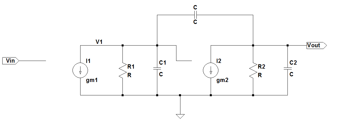
The 2 stage amplifier is modeled as shown below:
For this circuit the transfer function is given as:
So the poles are:
When we add the Miller Compensation capacitor the circuit becomes:

Solution
The equations for the above circuit can be written as:Solving the 2 equations to eliminate $V_1$ to get the transfer function we get:
Now that is a big expression and does not give much intuition about what factors dominate the pole values. The zero can be seen easily which is the famous RHP zero:
To get the poles let us equate the denominator to 0
If we substitute the following:
we can write (3) as:
We can solve for s as:
Now to simplify further we need to see the relative magnitudes to decide what terms can be neglected. Comparing A and B we can clearly see that if the circuit time constants are lower than even a milli second A ≪ B. That is because A is a product of 2 time constants while B is a time constant multiplied by the gain of the output stage $g_{m2}R_2$ that is the 1st term in B. Consider a time constant of 1ms. So A=1e-6 and B=1e-2 considering the output stage has a gain of 10. So 4A = 4e-6 and
$B^2$=1e-4 so $B^2$ is still 25 times larger than 4A. Considering that in actual circuits the time constants are in micro seconds and gains are usually 10-100 we can safely say that 4A ≪ $B^2$. So from this point on the assumption and approximation that we take is:
- The time constants in the circuit are of the order of 1ms or lower
- The Gain of the output stage > 10
OR
where τ = Time constant seen in the circuit
G = Gain of the stage across which the miller cap is placed
Note that these 2 conditions ensure indirectly that 1 pole is much lower in value than the other pole.
So now we can approximate the poles now as:
So substituting the values of A and B in we get the final poles of the circuit as:
The 1st pole is very close to the pole approximated by the miller approximation pole as mentioned in this article:
The second pole can be further approximated as:
Now if
$C≫C_1$ and $C≫C_2$ i.e the added miller cap is greatly larger than all parasitic caps then the second pole reduces to:which is what this note said.