Description
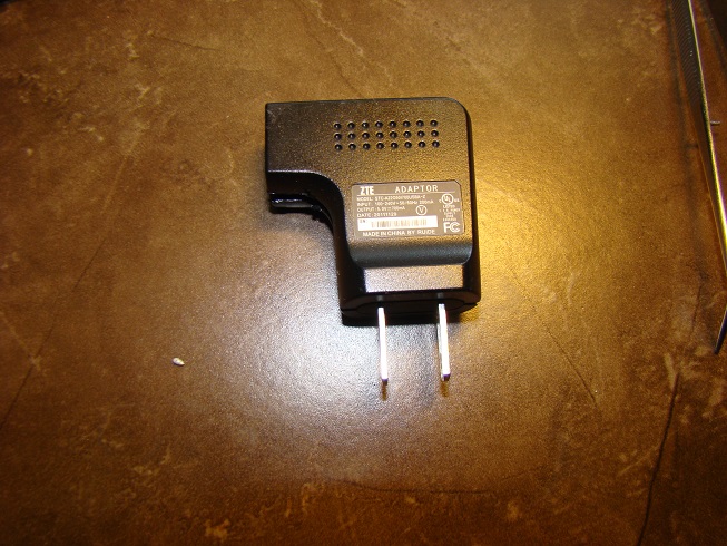
This is a USB charger that came with one of my Android phones to provide an output of 5V, 700mA which is good for powering the USB port on the charger. From the outside the charger looks like:
Internals
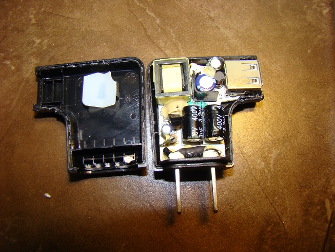
After prying it open from all sides (it was glued together) we see the circuit board with all the components:
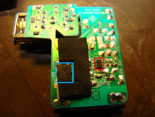
Turning it over we can see the controller IC (Red) and a bridge rectifier(Blue) (datasheets linked below)

The top marking on the bridge rectifier says MB6F which is a 600V (peak) 0.5A bridge rectifier which precedes a transformer. The top marking of the controller chip corresponds to the ACT361 controller IC. The power transistor is the KTC3003HV NPN transistor.
Circuit
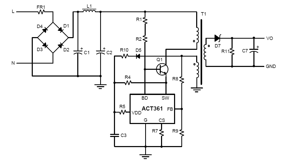
The circuit may be similar to the one shown in the ACT361 datasheet