Opamp Design and Analysis
Gain and Transconductance
- Gm of Differential Amplifiers: This note analyzes the Gm of a differential pair as loaded with a differential output load and a differential to single ended load.
- LDO Gain limiting resistor placement. 2 Schemes for putting an LDO gain limiting resistor are analyzed.
- Folded Cascode Analysis. A very interesting folded cascode analysis concentrating on the impedance seen by the signal on the fold nodes.
- Differential Amplifier full Gain calculation: Very rigorous small signal analysis for the differential amplifier transfer function containing everything. This composite expression can be simplified to get many cases and expressions.
Mismatch and Offset Analysis
- Input Offset for Folded Cascode Diffamp with MOS load: General analysis of mismatch of all folded cascode components referred to the input of the amplifier to easily calculate its offset.
- Offset Analysis of the Mirrored Transconductor: Offset components of a mirrored transconductor topology.
- Offset Analysis of 2 diff stage comparator: This analyzes a 2 differential stage comparator which is followed by a folded stage to give the output.
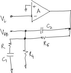
- Offset and Bandwidth of Opamp Based Differential Amplifier: Very useful derivation showing how the offset and pole of an opamp transform to the system offset and pole when used as a difference amplifier topology.
Frequency Analysis
- As a rule of thumb the highest unity gain frequency you can try to achieve for a opamp is ft/10. ft is the unity gain transition frequency of the device in the process at which the current gain from input to output is 1.
- Single Pole Opamp in feedback - This analysis plots the opamp Bode plot the Loop gain bode plot and the Transfer function bode plot together and analyses them.
- Transient Time constant of a circuit related to poles : A very useful derivation relating transient response characteristic of a single and a double pole system.
- Single Pole system in Unity Gain feedback, step response : As a extension to the previous derivation, this shows the time domain characteristics when a single pole system is in unity gain feedack.
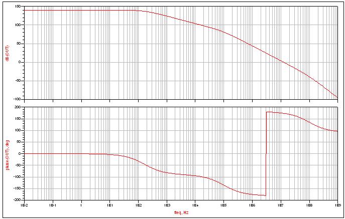
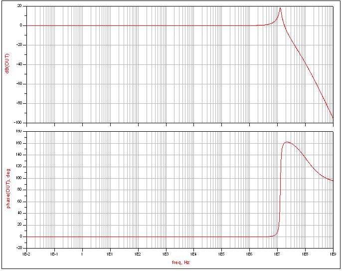
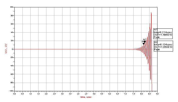
- 3 Pole Opamp in feedback - This analysis takes a 3 pole system which would be unstable in unity gain feedback. The 180 deg phase shift frequency is 2-3MHz but the unity gain oscillates at 12.5MHz. The bode plot for open loop is:
-
- Closed loop response is:
-
- Step response is:
-
- Circuit used to simulate the above responses is:
-
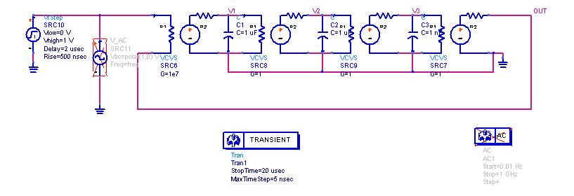
- The oscillation frequency will of course be the frequency where the denominator of Hf(s) goes to 0. That goes for 3 roots. The real root combined with the real part of the complex conjugate roots will be the exponential amplitude increasing function, the complex conjugate roots are the ones which will give you the oscillation frequency from the imaginary part (The jw axis)
-
Compensation
- Gm Amplifier with Lead Lag Network loading
-

- Important design observation that the zero should be placed near about the GBW of the loop to get any advantage from the network. See also Compensation Techniques
-
- Opamp Lag Lead Network analysis
- Various compensation techniques Analysis
- Always remember that compensation networks that depend on active circuitry to perform common example being miller compensation always create problems in startup\shutdown in the case when the active circuitry is not biased properly. So always before the main circuitry startup the active circuitry in the compensation network should be pre-biased for stable startup.
- Ahuja Compensation derivation - Derives the poles of Ahuja compensation scheme and also looks at the advantages over Miller Compensation.
Opamp Application
- N Input Differential Amplifier: Analysis of an N-Input differential pair and its equations that can be used to design
See Also
- Dynamic Analog Circuits (Contains Offset cancellation) Baker, Boyce, Li page 438
- Chopper Stabilized, Auto Zeroing and Correlated Double Sampling techniques for creating precision opamps
